Custom Filtered Connector Builder
Featuring Quell EESeall® Filters
Step 1 of 10
| C | Non-conductive, anodic coated aluminum, 500 hour salt spray, 200°C | |
| F | Electroless nickel plated aluminum, optimum EMI shielding effectiveness -65dB @ 10GHz specification min., 48 hour salt spray, 200°C | |
| G | Space grade, electroless nickel, 48 hour salt spray, 200°C | |
| K | Corrosion resistant stainless steel, firewall capability, plus 500 hour salt spray resistance, EMI -45dB @ GHz specification min., 200°C | |
| L | Corrosion resistant steel, electrodeposited nickel, 48 hour salt spray, 200°C | |
| W | Corrosion resistant olive drab cadmium plate aluminum, 500 hour extended salt spray, EMI -50dB @ 10GHz specification min., 175°C | |
| Y | Hermetic seal, passivated stainless steel, 200°C | |
| S | (Non-hermetic connectors) Nickel plated stainless steel, optimum EMI shielding, effectiveness -65dB @ 10GHz specification min., 500 hour salt spray, 200°C | |
| N | (Hermetic connectors) Nickel plated stainless steel, 200°C |
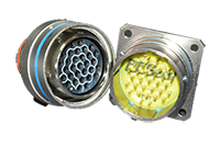
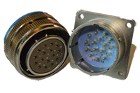
The Shell Size and Insert Arrangement determines the size of your connector, as well as the number and type of contacts present. Below is a reference table that shows standard Shell Sizes and their matching number. Also, you will be able to preview what your Insert Arrangement will look like, and how the contacts are arranged inside.
To Visualize All Insert Arrangements Click Here
| Shell Size Reference Chart | |||||||||
|---|---|---|---|---|---|---|---|---|---|
| A | B | C | D | E | F | G | H | J | |
| 9 | 11 | 13 | 15 | 17 | 19 | 21 | 23 | 25 | |
| Contact Legend | |||||
|---|---|---|---|---|---|
 8  10  12  16  20  22D |
|||||
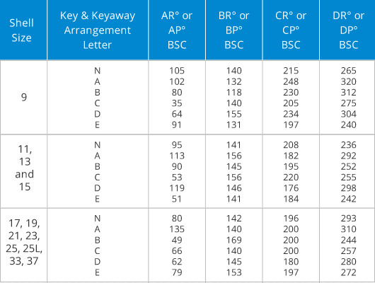
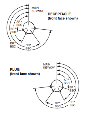
A plug with a given rotation letter will mate with a receptacle with the same rotation letter. The angles for a given connector are the same whether it contains pins or sockets. Inserts are not rotated in conjunction with the master key/keyway. Use N for Normal Position.


For lightning or transient voltage applications, please contact the engineering team for a custom recommendation.
List any pins with sensitive signals. This allows for a mixed-capacitor design.